This describes the difference between the three version of this circuit board and which products could use the particular board. This board is used for SRC162, SIC24, SC82, CSC and proposed WSMC.
Also information about three (3) wire device connections.
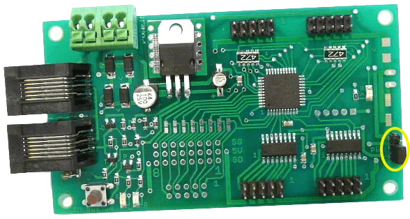
Version e is used for the SRC162e. Notice the the three pin connector with shorting bar indicated with the yellow circle. This selects either 5 volts or 12 volts. The 12 volt selection is used only for MotoDs.
The two output drivers will be damaged is used with 12 volts.
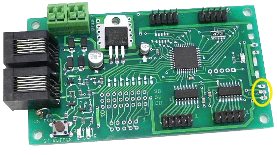
Version e is used for the SIC24e. Notice the area indicated with the yellow circle. A soldered shorting bar is use to permanently select 5 volts. This would apply to any products other than the SRC162.
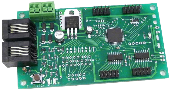
Version f is the same as version e with the additional feature of the capability of turning on and off the 5 volt servo power. It could be used for all products.
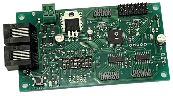
Version g is similar to version f with the special feature of supporting a three (3) wire type devices (Touch Triggers by Berrett Hill or Button Quik-Link by RR-CirKits).
This might be desirable for the SC82g and the WSMC. The 10 pin connectoe next to the 3 wire connector can be use instead of the 3 wire connector.
For the WSMC the two output drivers would not be required. The switch machine has its own outputs for LED indication.
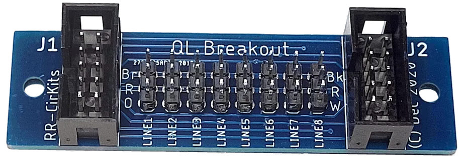
An alternative to having two versions of the Multi_IO board to support 3 wire interface devices is to use a breakout board. Only one version of the Multi_IO board would be required.
This board could be used to support 3 wire devices for the SMD84 with some resistor values and software changes.
