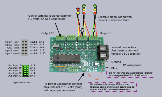
16 High current outputs, 200mA
13 Inputs for block and switch status
66 Logic cells 16 of which have physical outputs, 1 logic cell for each output
Powered with only DC, NOT DCC
Programming the same as CSCe except only 13 inputs
DecoderPro with CSCe as roster template is used for programming
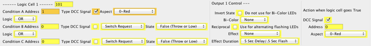
The first 16 logic cells must be programming specific to the output with the signal address and color. That is, they define the color and address of the signal connected to their respective output. For example, if output one (controlled by logic cell 1) is connected to signal 1 red, then Condition A would have an address of 1 and an aspect of red. Condition A is used for a solid color signal.
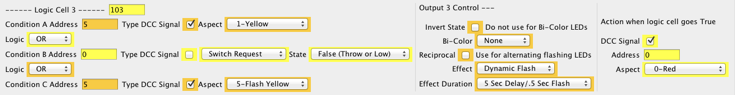
Another example, if output 3 (controlled by logic cell 3) is connected to signal 5 yellow, then Condition A would have an address of 5 and an aspect of yellow. If signal 5 has to flash yellow then Condition C would have an address of 5 and an aspect of flash yellow and dynamic flash must be selected in the Output control section. If a flashing color is required Condition C must be used with dynamic flash selected. Condition B is not used.
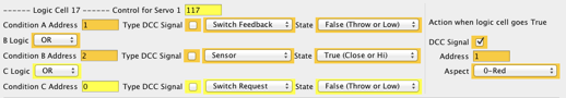
Logic cells 17 and above can be used for signal logic. For the logic to control an output set the address and aspect in “Action when logic cell goes True” just like in other CSC programming. For example, logic cell 17 controls signal 1 aspect red.